Packing/Unpacking
The wooden crate holding the locomotive can easily be modified to make a carrying case. Remove the two wooden blocks on the base and glue down a couple of wood strips in the center for rails (spaced 1.75” apart, of course.) Put an easily removable but strong strap around the crate where the original straps were, and lift with them so that the underside of the base is supported.
If you wish to add a handle, ensure it is firmly attached to the base with straps or similar supports. We do not recommend relying on the top of the wooden crate to support the entire weight of the engine!
The large foam padding will fit along the sides of the engine as it has no protruding parts (unlike the tender!) A couple of the internal straps will hold the engine securely in the crate.
Note! On the left front end of the tender tank is the drain cock. Take care not to knock it when packing/unpacking the tender
Assembly & Disassembly
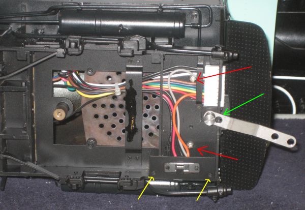
The supplied instructions show the screws that hold the engine and the tender body to their respective frames. The engine also requires that you disconnect the reversing lever, (red arrow, right,) and carefully tap the pilot braces out of their holes. The sand pipes will still protrude below the boiler, so handle with care.
There is one item incorrect with the instructions for the lead truck.
Insert the shoulder screw through the pilot truck frame and place the spring over the screw.
The spacer goes against the under frame of the engine. Insert the screw through the spacer and tighten it.
The engine-tender drawbar has two holes at the tender for handling wide (nearer hole) or sharp curves. There are also two holes under the cab, and the second hole (green arrow in the photo below) allows the engine and tender to be prototypically close-coupled with the rubbing blocks touching. We do not recommend altering the drawbar to this setting unless the engine is intended for static display.
Electrical
The following is the wiring schematic for the 10-pin connector between engine and tender.
1 |
Black |
Backup light |
2 |
Black |
Track power to tender (attached to motor and track leads.)
Note: Disconnect from motor leads in engine to use for speaker power from tender |
3 |
White |
Backup Light |
4 |
Grey |
Motor Lead Negative |
5 |
Brown |
Sound Cam |
6 |
Blue |
Sound Cam |
7 |
Green |
Lighting |
8 |
Yellow |
Lighting |
9 |
Orange |
Motor Lead Positive |
10 |
Red |
Track power to tender - same as 2 |

The switch under the cab (see photo above) connects track power to the motor or connects the motor to the tender power source.
There is a mistake in the wiring of the switch - the motor and track wires are reversed. This has no effect if you are using track power, but if the switch is pushed rearwards, the motor is isolated. Remove the panel holding the switch (yellow arrows on the above photo,) and reverse the wires on the forward two pairs of pins, so that the black (track) wires are connected to the front of the switch and the colored wires (motor) connect to the center pins.)
Sound
As shown in the above photo of the underside of the cab, the firebox floor is perforated and designed for installation of a 2.5 inch or less diameter speaker. There is a cam on the fourth axle with 4 contacts to provide the chuff signal to a sound card.
There is plenty of room in the boiler and firebox for sound electronics, or it can be fitted in the tender, along with batteries, radio control receivers, etc.
Rough Track
The locomotive operates exceptionally well on smooth track, but is long and a little stiff. On an outdoor layout that is more undulating, you may find the stiffness lifts the rear driving wheels off the track in a dip and/or causes derailments. It has been reported that the rear truck is particularly strongly sprung.
This photo of the rear truck mounts shows the front screw and spring, plus the rear plunger that rides on the cab floor. (There is a third screw and spring visible in front of the axle running in a slot that limits side movement.)
As delivered, the front spring is very tight, so you may elect to shorten it or leave it off completely. (The engine in this photo has a softer spring fitted by the owner on the forward screw.) For even more flexibility, at least one owner has removed the plunger at the rear - a quick twist with pliers will break it out of the hole in the crossbar.
|


